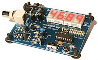
The features of the frequency counter :
- operating frequency range from about 15Hz to 8MHz (sufficiently high to make the counter useful for troubleshooting digital circuits, microcontrollers etc.)
- internal accuracy ± 1Hz
- 4 digits of displayed accuracy (enough accuracy for most situations)
- adaptive (no range switch)
- input conditioning amplifier sensitive to 50mV
- input protection
- crystal controlled (therefore no need for calibration)
- powered by a single 9V alkaline battery
The frequency counter / meter circuit can be divided into three main parts - the power supply, the input amplifier, and the digital circuitry.
Power Supply
The meter is intended to be portable and can be powered by a 9V alkaline battery. A voltage regulator is used to stabilise the supply rail to 5V. It is important for accuracy that the microcontroller has a good power supply and the regulator does this very well.
Input Amplifier
The input amplifier is the interface between the input signal and the PIC microcontroller, and its function is to condition the signal before it passes to the RTCC pin. It will convert any periodic signal (sine, triangular, square wave etc.) with a peak to peak amplitude of at least 50mV into a clean 5V TTL-level square wave as required by the RTCC input. The amplifier has a high input impedance to minimise its effect on the input signal.
Digital Circuitry
A standard power-on reset circuit is provided for the PIC. Components C8 and R13 hold the voltage at MCLR near zero volts until the PIC's oscillator has stabilised. Resistor R14 protects against C8 discharging through the MCLR pin, and diode D3 enables the capacitor to discharge quickly when power is removed.
Frequency Counter Component List
Resistors (all 1/4W 5% carbon film)
R1,R9 1k (brown, black, red, gold)
R2,R10,R11 470R (yellow, purple, brown, gold)
R3,R13 10k (brown, black, orange, gold)
R4 1M (brown, black, green, gold)
R5 2k2 (red, red, red, gold)
R6,R8,R15 220R (red, red, brown, gold)
R7 10R (brown, black, black, gold)
R12 560R (green, blue, brown, gold)
R14 100R (brown, black, brown, gold)
R16-R23 330R (orange, orange, brown, gold)
Capacitors (electrolytics 2.5mm spacing, others 5mm)
C1,C4,C6 100u electrolytic 16V
C2,C5,C7 220u electrolytic 16V
C3 100n miniature polyester
C8,C11 100n ceramic
C9,C10 22p ceramic
Semiconductors
TR1,TR3,TR4 BC549B npn transistor (or BC547B, 48C etc.)
TR2 BF244A or B N-channel JFET
TR5 ZTX313 npn switching transistor
D1-D3 1N4148 silicon diode
D4 BAT42 Schottky diode
REG1 LP2950 5V regulator
IC1 18-pin DIL socket + PIC16C54 HS/P microcontroller
DISPLAY1,2 0.56" dual 7-segment LED display, common cathode
Miscellaneous
X1 20MHz crystal, HC-49/U case
S1 miniature pcb vertical slide switch, SPDT
INPUT BCN pcb socket
BATTERY PP3 battery snap
4 x rubber feet
Download : source code text file frequency counter / meter schematics PCB Foil Pattern PCB Silk Screen
Source : http://www.apogeekits.com/counter_article.htm


Hiç yorum yok:
Yorum Gönder